Step 11 - Create Door Cutouts
The next step is to create the cutouts where the doors will go. The cutouts are nothing more than white filled rectangles that cover the wall where the doors will be located and are added to make the walls invisible in that location.
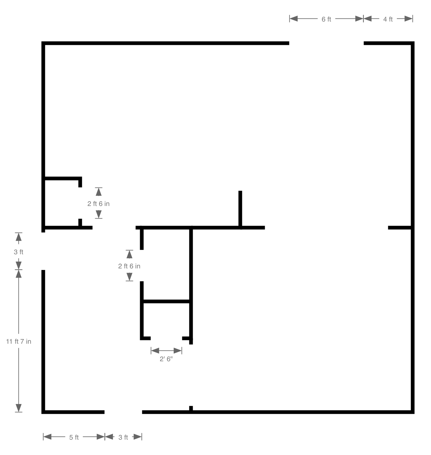
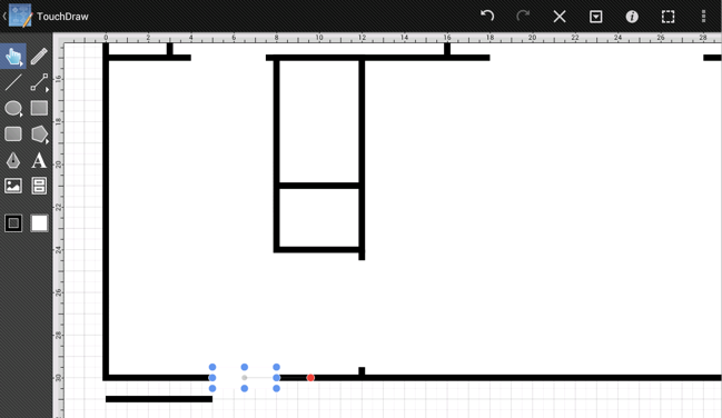
We created the following diagram (also done as an additional layer within the TouchDraw drawing) in order to provide a guide as to where the cutouts should be placed:
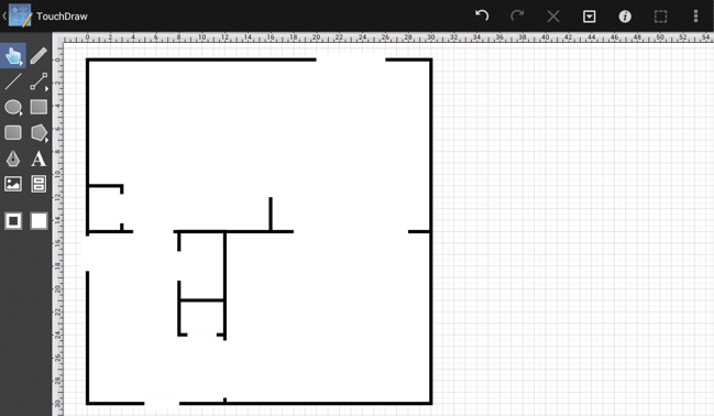
For this type of work, it is often best to zoom in on the area where the work will be performed. Zoom in on the front door and foyer closet portion of the drawing since the cutouts for these areas will be added first.
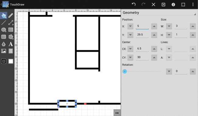
First, the front door is 5 feet from the left, so a temporary line must be drawn as a point of reference.
Next, use the Rectangle Tool to draw the cutout.
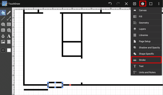
The rectangle was drawn with the current stroke setting (which was 6 points and black), so a few stroke attribute changes will be necessary before continuing.
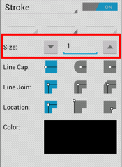
First, bring up the Info Menu, tap on the Stroke option, and change the the Stroke Size from 6 to 1.
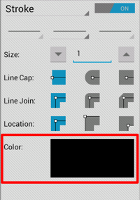
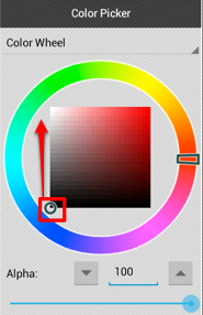
Next, change the stroke color to white by tapping on the Colorattribute in the Stroke Panel. Once the Color Picker opens, grab the handle in the color square and then drag it to the upper left hand corner.
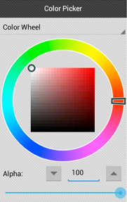
After dismissing the Stroke Panel, you will see that the cutout is now styled correctly (with a white stroke and a white fill).
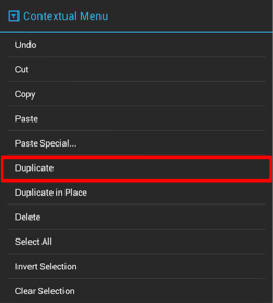
Next, duplicate the cutout and drag the copy to where the foyer closet door should go. To duplicate a shape, first make sure it is selected and then either touch and hold on the figure or press the Contextual Menu Button in the Top Toolbar to bring up the Contextual Menu.
This action will create a duplicate that is slightly offset from the original.
Then touch within the bounds of the copy and drag it to where the foyer closet door should go.
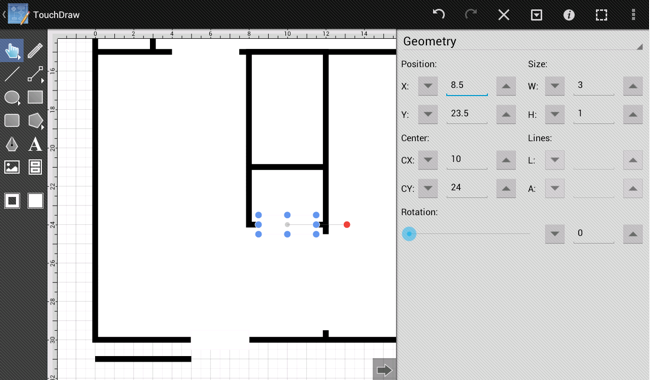
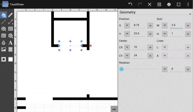
You will notice that the cutout has been centered within that wall; however, it will need to be made smaller as that door should be 2ft 6in. For this adjustment, the easiest thing to do is to grab the left center handle and move it over 3 inches, and then grab the right center handle and move it to the left 3 inches.
Note: At this zoom level there is a grid stop every 3 inches (1/4 of a foot), which makes the above adjustment easy. If we were to zoom in further, grid stops would appear every 1 inch.
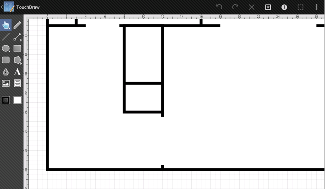
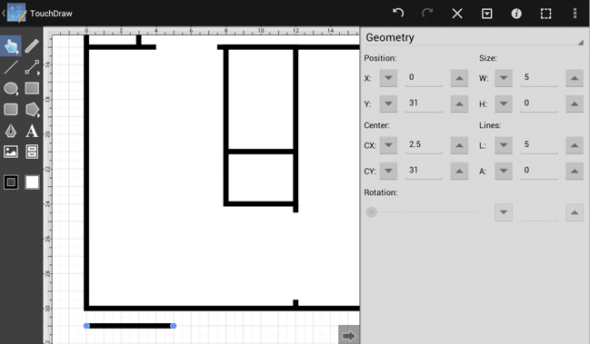
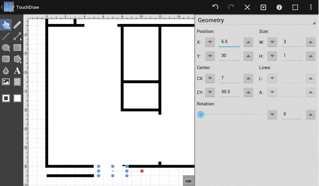
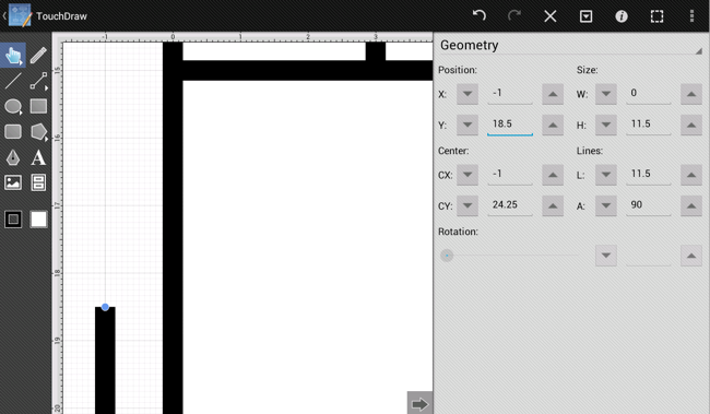
Next, move onto the side door. As seen in the example above, this door is 11 ft 7 in from the lower left hand corner. Since a temporary line already exists on the drawing, we will just drag the handles and re-use it for the side door as well.
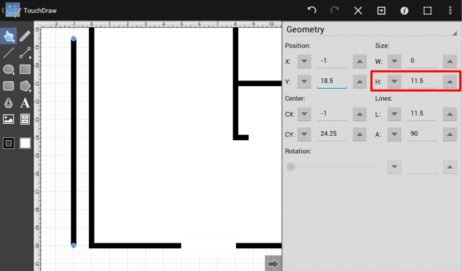
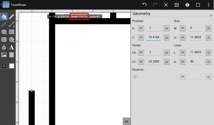
At the current zoom level, the line can be dragged up 11.5 ft (11 ft 6 in); however, we will need to zoom in more to extend that temporary line the final 1 inch.
As the temporary line is dragged, you can look at the info bar that pops up to make sure it is dragged to the correct length.
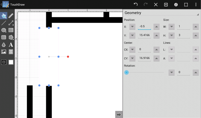
Next, create the cutout rectangle for this door using the Rectangle Tool.
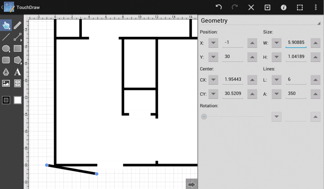
Select and delete the temporary reference line and create the cutouts for the rest of the doors by using the same process as above to generate the result shown below: